Talk:Schmitt trigger
| WikiProject Electronics | (Rated Start-class, Mid-importance) | ||||||||||||||||
|---|---|---|---|---|---|---|---|---|---|---|---|---|---|---|---|---|---|
|
|||||||||||||||||

Contents
- 1 Rewrite
- 2 Circuit is faulty.
- 3 regenerative comparator?
- 4 inadequate explanation
- 5 Schmitt trigger or Schmitt-trigger?
- 6 Digital/Software implementation?
- 7 Applications?
- 8 "Wrong image" is wrong.
- 9 Schmitt trigger with emitter output
- 10 About the relation between hysterisis and positive feedback
- 11 Rewrite 2
- 12 Does the non-inverting Schmitt trigger exhibit negative resistance?
- 13 Is there a virtual ground in a non-inverting Schmitt trigger?
- 14 Removing refimprove tag
- 15 Questions and comments
Rewrite[edit]
I can't see that the recent rewriting has improved the article all that much, if at all. The explanation of what the device is is now somewhat obscured by the way it has been reworded - for my money the previous explanation was a better overall summary and easier to understand. Also, the mention that the device has memory is erroneous - it does not. What it does have is positive feedback, which is something altogether different. Further, there is no requirement that a schmitt trigger circuit has to also invert the input - while a typical op-amp based one will do this, non-inverting designs are also possible. While the original text can no doubt be improved upon, I don't feel this effort has achieved that. We must always write for a lay audience and avoid bringing in extraneous details in an opening paragraph - the essence of an explanation is all that is necessary and desirable. Can we have another go please? Graham 04:19, 10 October 2005 (UTC)
- That was my rewrite, and feel free to change it or completely trash it if you like. Regarding specific points:
- Obviously, I thought my changes made it easier to understand. If you disagree, please change.
- The positive feedback causes it to have memory. ("Memory" simply means that the present state/output can depend on past inputs as well as the present one. The Schmitt trigger has memory because when its input is between the two threshold voltages, its output depends on past values.)
- You're right about inverting vs. non-inverting Schmitt triggers. I screwed up a bit: my goal had been to explain what a Schmitt trigger does by explaining what an inverting one does, and then explaining that non-inverting ones exist as well. I then forgot to include the explanation that non-inverting ones exist as well. (And thinking about it, it would probably make more sense to explain non-inverting ones first, and then to mention that inverting ones exist and are more common nowadays.)
- I don't understand what you're getting at with your statement that "we must always [...] avoid bringing in extraneous details in an opening paragraph"; the first paragraph of both versions is the same, and the second paragraph of my version has no details that the second paragraph of the older version lacked.
- I think what's really needed is a graph demonstrating a typical trigger's I/O characteristic; text is always rather opaque compared to a figure. But again, feel free to make any change to my text that you want to make, or to revert my edit if it really bothers you. Ruakh 10:51, 10 October 2005 (UTC)
- I don't wish to trash it, or even revert it - it's better to move the article forward where we can. Overall it's not too bad. I accept your argument about memory, I suppose it's fair enough to consider it in that way, though I hope that this isn't causing a muddle (it isn't to electronics experts of course, but that's not who we are writing for - they already know this stuff and so can interpret accordingly. A lay reader might think this had something to do with digital type memory, in which case this might be a bit confusing!) I completely agree that a graph would speak a thousand words. The inverting/non-inverting is a minor issue that can be easily fixed up. I might have a go one of these days! Graham 11:58, 19 November 2005 (UTC)
- It's not clear to me why I should use Schmitt trigger or a simple comparator. Look it this: http://www.deetc.isel.ipl.pt/electronica/LEIC/FAE/componentes/semicondutores/biblio/03_opamp.pdf Cyro Carvalho —Preceding unsigned comment added by 189.115.251.173 (talk) 02:09, 25 May 2010 (UTC)
Circuit is faulty.[edit]
The given circuit diagram isn't a Schmitt trigger, it's just a simple inverter, or digital inverter. Ie, it has no hysteresis. For a Schmitt trigger, you need the feedback to affect the reference voltage. A 'correct' example is this one: http://hyperphysics.phy-astr.gsu.edu/hbase/electronic/schmitt.html
I'll have a look at fixing this myself sometime :) --Ch'marr 11:03, 22 December 2005 (UTC)
- AFAICS, the diagram is OK. The circuit will exhibit hysteresis, and it is not an inverter (the input is connected to the non-inverting input of the comparator). A schmitt trigger does not require that the feedback affects the reference voltage, though that is certainly one way to build one. (By the way, that link appears to be dead). Graham 00:25, 23 December 2005 (UTC)
- I respectfully disagree. That circuit will not exhibit hysteresis. As soon as Vin transcends the reference voltage (unmarked in the diagram), the output voltage will hit Vs+ or Vs-. (I'm assuming a comparitor is being used, but you can achieve the same effect by reversing the inputs of a standard op-amp). To have hysteresis, the reference voltage for a positive transition, and a negative transition, needs to differ. Eg: For L-H, Vin >3V, for H-L, Vin<2V. The circuit in my link (which does work) does that... and I realise it's a link to the same place as the 'External Links' :)
- So, I ask that we change the diagram to something similar to that found in the link... unless we can find another implementation that shows it to be as simple as the one in the wiki page right now. --Ch'marr 00:16, 25 December 2005 (UTC)
- Okay, colour me stupid, that will work if that's actually a comparitor rather than a standard op-amp. But it assumes that Vs- is lower than the reference voltage. --Ch'marr 00:25, 25 December 2005 (UTC)
- I'm not sure what distinction you're drawing between a comparator and an op-amp - while circuits may be optimised for one application of the other, in essence there is no difference. So your remarks about 'reversing the inputs' don't mean anything sensible to me. The circuit pictured is probably not the most ideal design to be honest, but will exhibit hysteresis as long as it is driven from a low source impedance. We also need to choose our resistors so that the feedback resistor is somewhat larger than the input resistor. Assume the output of the circuit is in the low state. The resistor network forms a potential divider to the -ve supply rail. (and yes, I would assume that the -ve supply is more negative than ground, which is not unreasonable, as most op-amp basic circuits are shown with this arrangement in mind). The input needed to flip state will therefore be somewhat higher than Vref. Once it reaches this value, the comparator will flip, its output going high. The resistor network now forms a potential divider to the +ve supply rail, so to bring the + input back below the value of Vref will require that the circuit input is brought down much lower than the original L->H trip voltage. The only reason I say that a low source impedance is needed is because it must be able to sink or source the required current into the potential divider without a significant change in its own voltage, otherwise it won't perform very well. So we just need to choose the input resistor to be large enough to make sure this doesn't happen. Now I'm not saying this is the best circuit for the job - certainly by arranging the feedback to alter the reference voltage rather than the effective input voltage is probably a better approach, but there's no reason that this wouldn't work and it's easy to understand.Graham 08:47, 25 December 2005 (UTC)
- Yep, I see all that now, thanks for the explaination. I think I'm just so used to seeing the schmitt trigger set up in the same way as the link above that anything else looks weird and makes my brain explode :) I still maintain that the other circuit is a little easier to see what's happening, and more flexible (not requiring a deviation from ground). But... that's just me being petulant. Feel free to zap this section of the discussion, since it's wrong/moot. --12.104.153.15 01:59, 28 December 2005 (UTC)
- I'm not sure what distinction you're drawing between a comparator and an op-amp - while circuits may be optimised for one application of the other, in essence there is no difference. So your remarks about 'reversing the inputs' don't mean anything sensible to me. The circuit pictured is probably not the most ideal design to be honest, but will exhibit hysteresis as long as it is driven from a low source impedance. We also need to choose our resistors so that the feedback resistor is somewhat larger than the input resistor. Assume the output of the circuit is in the low state. The resistor network forms a potential divider to the -ve supply rail. (and yes, I would assume that the -ve supply is more negative than ground, which is not unreasonable, as most op-amp basic circuits are shown with this arrangement in mind). The input needed to flip state will therefore be somewhat higher than Vref. Once it reaches this value, the comparator will flip, its output going high. The resistor network now forms a potential divider to the +ve supply rail, so to bring the + input back below the value of Vref will require that the circuit input is brought down much lower than the original L->H trip voltage. The only reason I say that a low source impedance is needed is because it must be able to sink or source the required current into the potential divider without a significant change in its own voltage, otherwise it won't perform very well. So we just need to choose the input resistor to be large enough to make sure this doesn't happen. Now I'm not saying this is the best circuit for the job - certainly by arranging the feedback to alter the reference voltage rather than the effective input voltage is probably a better approach, but there's no reason that this wouldn't work and it's easy to understand.Graham 08:47, 25 December 2005 (UTC)
- Standard notation calls for transistors to be Q (Q1, Q2...). T is used for transformers. —Preceding unsigned comment added by 206.174.35.213 (talk) 08:24, 24 April 2008 (UTC)
Agreement with the original comment from December 2005. As of April 10, 2010, the circuit shown here is a simple inverting amplifier, with gain of -R2/R1. In the range for Vin mentioned in the article, i.e., Vin in the range of +/- R1/R2*Vs, the circuit shows purely linear amplification. Beyond that range, the circuit simply clips at Vs. There is no hysteresis, and the circuit therefore cannot be called a Schmitt trigger.
To form a Schmitt trigger, a third resistor is needed, to create a resistor divider between +/- Vs.
The link at http://hyperphysics.phy-astr.gsu.edu/hbase/electronic/schmitt.html seems to be working well, and shows a correct circuit. —Preceding unsigned comment added by 63.207.173.11 (talk) 21:42, 16 April 2010 (UTC)
- No, the circuit is ok. It's not an inverting amplifier. Oli Filth(talk|contribs) 08:50, 17 April 2010 (UTC)
regenerative comparator?[edit]
should it also be noted that it is also a regenerative comparator? Excuse me if I am not correct, but it appears to be the same thing.
- Yes, it's the same thing. Though a google search for "regenerative comparator" returns just 263 hits versus 364,000 for "schmitt trigger" and 25,400 for "schmidt trigger" so it's not a term used very much at all, and to me sounds like technobabble. I don't think we should encourage the use of this wordy term for such a common circuit by giving it a wikipedia endorsement. Graham 12:00, 15 March 2006 (UTC)
inadequate explanation[edit]
Could someone please better explain the purpose of resistor R4 in the figure at http://en.wikipedia.org/wiki/Image:Opampschmitt_realistic_xcircuit.png . The current explanation is "R4 has to limit the current due to the offset voltage on the input of the amplifier". I do not understand why R4 is needed at all. Thanks.
In an actual comparator, especially with bipolar transistor inputs, a small bias current is often required by both inputs. If the small bias current was zero, then R4 would not be needed. Normally, the bias current needed for each input is about the same, and changes such as temperature cause both input bias currents to increase or decrease together. Note that if the positive input has a small bias current, that current arrives through resistors R1 and R2, causing a small additional voltage drop in those resistors. By adding R4, we try to create the equivalent voltage drop at the negative input. The goal is that if the voltage drop is the same for both inputs, the voltage drops cancel each other out. Thevenin says that the value of R4 in ohms is equal to the computed value of R1 and R2 as if they were hooked up in parallel. —Preceding unsigned comment added by 99.169.132.203 (talk) 04:50, 28 April 2009 (UTC)
Schmitt trigger or Schmitt-trigger?[edit]
What is the correct way to write it, Schmitt trigger or Schmitt-trigger (with a dash)? Jidan 13:19, 26 December 2006 (UTC)
- No dash. It's an inventor's name, I don't think there is a dash in the article. — RevRagnarok Talk Contrib 15:52, 26 December 2006 (UTC)
- Are you sure? Because I have seen many textbooks using the dash. Also in the german wikipedia, its written with a dash [1]. Jidan 16:31, 26 December 2006 (UTC)
- Fairly sure. All my textbooks that would apply are at work. And for the German one, it may be hyphenated because it is a compound "import" word. I know no German, but assume that trigger is not the German word, so the two words together have been imported. — RevRagnarok Talk Contrib 18:41, 26 December 2006 (UTC)
- I don't think it has to do with the language. I still think that it should be written with a dash, since both words are dependant on each other. Another good example is Real-time. Jidan 01:07, 29 December 2006 (UTC)
- But we don't normally write Fourier-transform, or Kelvin-scale, or Pythagorean-triples. The example of real-time is different when used as an adjective (e.g. "This is a real-time system"), as it is a single concept. But the Schmitt trigger is a type of trigger which happens to be Schmitt, just as a brown dog is a dog which happens to be brown. Oli Filth 20:44, 31 December 2006 (UTC)
- Unlike scale in "kelvin scale" or brown in "brown dog", trigger is a verb.
- Trigger can be a verb ("I trigger the explosion") or a noun ("He pulled the trigger"). In this context, it is a noun.
- You say Time-Triggered Protocol, not Time triggered.
- Indeed I do, because in that context, time-triggered is an adjective.
- Digi-Key, one of the biggest component electronics supplier, calls it "schmitt-trigger" with a dash. [2]. Jidan 17:06, 1 January 2007 (UTC)
- On that page, in the "Logic type" column, they call it "Schmitt Trigger" without a dash. I don't think that we should take much notice of the "Description" colum, because "IC SGL SCHMITT-TRIG BUFF SC70-5" is clearly not real English.
- Unlike scale in "kelvin scale" or brown in "brown dog", trigger is a verb.
- But we don't normally write Fourier-transform, or Kelvin-scale, or Pythagorean-triples. The example of real-time is different when used as an adjective (e.g. "This is a real-time system"), as it is a single concept. But the Schmitt trigger is a type of trigger which happens to be Schmitt, just as a brown dog is a dog which happens to be brown. Oli Filth 20:44, 31 December 2006 (UTC)
- I don't think it has to do with the language. I still think that it should be written with a dash, since both words are dependant on each other. Another good example is Real-time. Jidan 01:07, 29 December 2006 (UTC)
- Fairly sure. All my textbooks that would apply are at work. And for the German one, it may be hyphenated because it is a compound "import" word. I know no German, but assume that trigger is not the German word, so the two words together have been imported. — RevRagnarok Talk Contrib 18:41, 26 December 2006 (UTC)
- Are you sure? Because I have seen many textbooks using the dash. Also in the german wikipedia, its written with a dash [1]. Jidan 16:31, 26 December 2006 (UTC)
- Clearly, in the context of this article's title, "Schmitt Trigger" is being used as a noun, and as such, there should be no hyphen, IMO. Oli Filth 20:42, 1 January 2007 (UTC)
- Tossing in my two cents, proper English would be the following.
- A Schmitt-trigger buffer uses a Schmitt trigger to clean up the buffered signal.
- Note that the word Schmitt only is capitalized and that the hyphen is used in the adjective form but not the noun form. Unless it can be demonstrated that the bad English version is so common as to be considered the standard (which I think has been shown to not be the case) the article should stick with good English.
- --Mcorazao 21:52, 2 January 2007 (UTC)
- Tossing in my two cents, proper English would be the following.
Digital/Software implementation?[edit]
The idea of the Schmitt trigger is also used in digital implementations, e.g., to detect transients in a digitally sampled signal, e.g., for audio onset detection. Does a "Schmitt trigger" have to be an analog circuit implementation as the article says? Is there another name for this general idea (i.e., the logic of having a high and low threshold, etc.) when implemented in some other way?
MusicScience 18:55, 9 October 2007 (UTC)
Ref [2] in the article shows Schmitt's original design, the essential feature being the use of two triodes with feedback provided by the common cathode connection. While the transistor version shown in the main article retains that structure with feedback via the common emitter connection, I would question whether the implementations using op-amps qualify as a Schmitt Trigger. Certainly they exhibit hysteresis but the feedback is via the base of the input stage transistor unlike Schmitt's design. The general name for differing thresholds is "hysteresis" but IMHO this article is about Schmitt's method, not hysteresis in general.
George Dishman 09:59, 22 June 2009 (UTC) —Preceding unsigned comment added by GeorgeDishman (talk • contribs)
Applications?[edit]
Is it possible to explain where this device is used in a common application we might recognize? A switch on an electronic device perhaps?Landroo (talk) 19:53, 5 April 2009 (UTC)
Noise rejection as explained in the article is undoubtedly the major benefit but the circuit is also used to improve the rise/fall time of slow edges and it is also used as a delay circuit by preceding a Schmitt with an RC filter.
George Dishman 10:00, 22 June 2009 (UTC) —Preceding unsigned comment added by GeorgeDishman (talk • contribs)
"Wrong image" is wrong.[edit]
I have removed the statement "(WRONG IMAGE! Should have a circle at the right point of the triangle indicating inversion!" from the inverting schmitt trigger picture. It is a correct image, as the symbol represents the graph of input voltage (X axis) vs output voltage (Y axis) with the origin (Vmin,Vmin) at the bottom left corner (as is standard for most graphs). The symbol describes that the output voltage at Vin=Vmin is high, but goes low when the input voltage is raised sufficiently. This is inversion. Adding a circle to the output (as is suggested by the comment) would invert the output of this gate, turning it back into a normal schmitt trigger. A normal schmitt trigger (not inverting) with a circle on its output is equivalent to the current picture, so it is possible that the editor did not notice the inversion of the response graph. —Preceding unsigned comment added by 118.208.106.219 (talk) 03:21, 9 October 2010 (UTC)
- Actually the picture is of a Schmitt trigger buffer (non inverting).
- Inverters always have the circle whether or not it is a Schmitt trigger.
- See http://www.fairchildsemi.com/ds/MM/MM74HC14.pdf for a datasheet for an inverting triger, note the circle.
- Also don't delete peoples posts on the discussion pages, how would you like it if I just deleted your post?
- 125.209.163.55 (talk) 10:02, 30 September 2011 (UTC)
- I have reverted your change. There is more than one conventional symbol for an inverting Schmitt trigger. As you will notice, the hysteresis curve in the symbol shown is inverting. If you favor Fairchild Semiconductor, then you should be convinced by the QSE158 datasheet. In particular, see the QSE157 totem pole output inverter in the upper-right quadrant of the page. The inverting Schmitt trigger is shown. In fact, the other diagrams depict a non-inverting Schmitt trigger as an inverting Schmitt trigger with a bubble (which is due to implementation details). —TedPavlic (talk/contrib/@) 16:14, 30 September 2011 (UTC)
Schmitt trigger with emitter output[edit]
I would like to discuss the text below about Schmitt trigger with an output taken from the emitter instead from the collector.
"This non-inverting Schmitt trigger can be turned into a inverting trigger and another resistor saved in the process, by replacing Rc2 with a short connection, and connecting Vout to the emitter of T2 instead of its collector. In this case however, a larger value of resistance should be used for RE as it now serves as the pull-down resistor on the output, lowering the voltage on the output when the output should be low, instead of a serving as only a small resistance which is only intended to develop a small voltage across it that actually adds to the output voltage when it should be at a digital low."
Why Rc2 is replaced with a short connection as it is needed to determine the high threshold? What will be the high threshold then? Why RE has to have "a larger value of resistance"? Conversely, a pull-down resistor has to have high enough resistance to "pull" the node downwards. Circuit dreamer (talk, contribs, email) 15:41, 9 November 2010 (UTC)
About the relation between hysterisis and positive feedback[edit]
I have copied the text below from Talk:Hysteresis to move here the so interesting discussion about the relation between the two great phenomena. Circuit dreamer (talk, contribs, email) 15:39, 13 November 2010 (UTC)
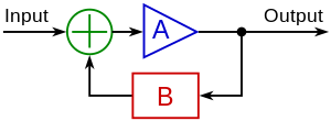
The two phenomena are closely related (at least, in the area of electronic circuits). Any amplifying circuit with positive feedback having a loop gain B.A > 1 possess hysteresis and v.v., any circuit with hysteresis is an amplifying circuit that is comprised by such a positive feedback. IMO it is impossible to separate them (to have a hysteresis without positive feedback and feedback without hysteresis); we can use positive feedback to obtain hysteresis.
A proportional (fully analog) thermostat is an amplifier (comparator) with only a "global" negative feedback (consisting of cascaded heater, an object and a thermo sensor). The comparator of the simpler bistable thermostat has in addition a "local" positive feedback that forces the transition between the two supply rails and creates the needed hysteresis. Another example: op-amp relaxation oscillator. But how does the positive feedback do this magic? How do we obtain hysteresis by applying feedback? How do we create dual-threshold circuits? How do we convert a one-threshold circuit into a two-threshold one?
Dynamic threshold. The first trick is very simple and intuitive - when the input voltage crosses the threshold in some direction the very circuit changes slightly its own threshold to the opposite direction (i.e., it subtracts voltage from the threshold that is equal to adding voltage to the input voltage). So, the output affects the threshold and do not impact on the input voltage. These circuits are implemented with differential amplifier with series positive feedback where the output is connected to the non-inverting input and the input - to the inverting input. In this arrangement, the humble loop forms the needed summing circuit in the figure (the circle with "+" inside). Examples: classic emitter-coupled transistor Schmitt trigger, op-amp inverting Schmitt trigger, etc.
Modified input voltage. The second technique is opposite - when the input voltage crosses the threshold in some direction the circuit changes slightly the very input voltage in the same direction (i.e., it directly adds voltage to the input voltage). In this case, the output affects (helps) the input voltage and do not affect the threshold. These circuits can be implemented by a single-ended amplifier with parallel positive feedback where the output and the input source are connected through resistors to the non-inverting input. Now, the two resistors form the needed summing circuit (the circle with "+" in the figure). Examples: collector-coupled transistor Schmitt trigger, op-amp non-inverting Schmitt trigger, etc.
From the feedback view, both the techniques above are the same - systems with positive feedback that is out of control. In both the circuit, the output voltage increases the derivative (difference) input voltage of the comparator (not of the whole circuit!) by decreasing the threshold or by increasing the circuit input voltage. The threshold and memory properties are incorporated in one element (two in one:)
Two different static thresholds. In this case, the threshold and memory properties are separated. The two different thresholds are created by separate ordinary open-loop comparators (without hysteresis) that drive an RS trigger (2-input memory cell). Again, there is a positive feedback but now it is concentrated only in the memory cell. Example: 555 timer. Circuit dreamer (talk, contribs, email) 22:25, 12 November 2010 (UTC)
Rewrite 2[edit]
This recent rewrite is very poor. Poor grammar, misspellings, and incorrect assumptions throughout. Zen-in (talk) 16:30, 14 November 2010 (UTC)
- Thank you for the "encouragement"; now, I am "inspired" to continue... You are welcome, as a native speaker, to correct the "poor grammar and misspellings", and, as a specialist, to correct the "incorrect assumptions" throughout the article where you can find them... Circuit dreamer (talk, contribs, email) 16:52, 14 November 2010 (UTC)
Does the non-inverting Schmitt trigger exhibit negative resistance?[edit]
Welcome, Oli! I am glad to see you again since Wikipedia is not so interesting without you:) My appeal to you is to be more constructive in your edits, to consider my edits before removing (not shoot first, ask questions later).

During the transition, an op-amp non-inverting Schmitt trigger is a typical Miller arrangement exhibiting negative resistance. IMO you are clever enough to realize this interesting fact. Let's consider the situation.
We have a resistive chain R1-R2 supplied by the input voltage from the left and by the output voltage from the right. Imagine the input voltage continuously increases. As the output voltage stays constant, the input current continuously increases as well and we have positive resistance. When the input voltage exceeds the high threshold, the output voltage begins changing vigorously in the same direction as the input voltage. The current begins decreasing vigorously although the input voltage continues increasing. Thus the input voltage increases while the current decreases; so, the circuit exhibit negative resistance. Look at the NIC on the right; a non-inverting Schmitt trigger is the same circuit where R1/(R1+R2) → 0. Regards, Circuit dreamer (talk, contribs, email) 17:02, 23 November 2010 (UTC)
- We've been through this sort of thing before. The instantaneous behaviour at the moment of transition cannot reasonably be called "negative resistance". Please provide a source if you disagree. Oli Filth(talk|contribs) 21:48, 23 November 2010 (UTC)
Is there a virtual ground in a non-inverting Schmitt trigger?[edit]
Yes, it sounds paradoxical but there is a virtual ground (V+ = 0 V) at the non-inverting input (for a moment) in two situations at that: when the increasing input voltage becomes equal to the high threshold and when the decreasing input voltage becomes equal to the low threshold. In both the situations we have the same resistive chain as above (the two connected in series resistors R1-R2) supplied by two voltages with opposite polarities (see this picture). Here R1.Vs = -R2.Vin and the intermediate point is at zero voltage. In other words, the virtual ground represents the zero output voltage of the parallel resistive summer with weighted inputs composed by the two resistors R1 and R2. Circuit dreamer (talk, contribs, email) 17:59, 23 November 2010 (UTC)
- We've been through this before. Virtual grounds don't exist in positive feedback situations. Just because it's momentarily 0V at transitions does not make it a virtual ground. I will be reverting this change, unless you can provide a source. Oli Filth(talk|contribs) 21:45, 23 November 2010 (UTC)
Removing refimprove tag[edit]
I'm inclined to remove the refimprove tag. It was place in 2009 with this edit. The article has been updated substantially since then, so I'm inclined to remove the refimprove tag unless there is something specific that is still lacking. Please discuss. 64.40.62.14 (talk) 04:21, 12 March 2012 (UTC)
- Removed tag per WP:BOLD. Please use {{fact}} for any specific concerns. 64.40.62.84 (talk) 03:13, 13 March 2012 (UTC)
Questions and comments[edit]
This article is not easy to read and comes to conclusions that are not so obvious to the reader. This article should be improved. I have a series of questions and comments.
1. The third and the fifth figures from the top have captions that are way to long. The information should probably be part of the text.
2. Several sentences in the "Fundamental idea" section are written in italics. If they are quotes from something that was written, maybe by Schmitt, they should have quotes and it should be pointed out where they come from.
3. Under the "Initial state" section I read "It is approximately equal to the high threshold and may not be low enough to be a logical zero for next digital circuits."
Should that "next" be "following" if there is a stage to the right of the circuit?
4. Under the "Crossing up the high threshold" section I read "This avalanche-like process continues until Q1 becomes completely turned on (saturated) and Q2 turned off" and "Q2 becomes completely turned on (saturated) and the output voltage becomes low again".
Shouldn't Q1 and Q2 be past the saturation region or in the active/linear region if "completely turned on"?
5. Under the "Direct-coupled circuit" section I read "In this case, the common emitter voltage and Q1 collector voltage are not suitable for outputs".
What's the reason for the conclusion? Also, is this for the non-inverting variation of the circuit?
6. Under "Collector-base coupled circuit", what's the meaning of "VBE0 ∞ 0.65 V"? Why is "0" used? Is "∞" used for proportional or should it be a "="?
7. Under the "Op-amp implementations" section I read "An open-loop op-amp and comparator may be considered as an analog-digital device"
If that is the case, shouldn't the device be called an "open-loop op-amp-based comparator mixed-signal device"?
8. The "Non-inverting Schmitt trigger" section says "The output voltage V+ of the resistive summer". The "Inverting Schmitt trigger" section says "The output voltage V+ of the voltage divider is".
This is really confusing because, after simulating both non-inverting and inverting configurations of the Schmitt trigger, it is clear that, for the non-inverting circuit, the thresholds are and for the inverting circuit, the thresholds are . If R1=5kΩ and R2=25kΩ then thresholds are respectively ±3V and ±2.5V.


Having said this, I do not understand what the wording about V+ in the non-inverting and inverting sections means (including "resistive summer" and "voltage divider" labels). To me the explanation is quite confusing. Also, I do not understand the meaning of .

I would suggest to revise the sections and use a single statement followed by for inverting and for non-inverting. It would also be nice to specifically state that the hysteresis for non-inverting is and inverting is , followed by the statement that says the hysteresis can be shifted by a DC voltage offset at the negative pin for non-inverting and the positive input pin for inverting.


9. Under the "Inverting Schmitt trigger" section I read "In contrast with the parallel version, this circuit does not impact on the input source since the source is separated from the voltage divider output by the high op-amp input differential impedance."
This sentense is unclear and needs to be revised.
10. The "Use as an oscillator" section says "A Schmitt trigger is a bistable multivibrator, and it can be used to implement another type of multivibrator, the relaxation oscillator."
This sentence seems to imply that the relaxation oscillator is a type of multivibrator when the truth is that the thing are actually reversed because a multivibrator is a type of relaxation oscillator.